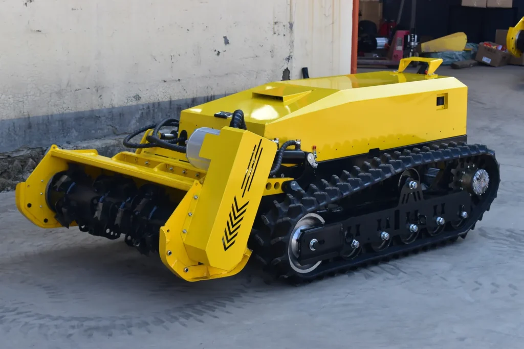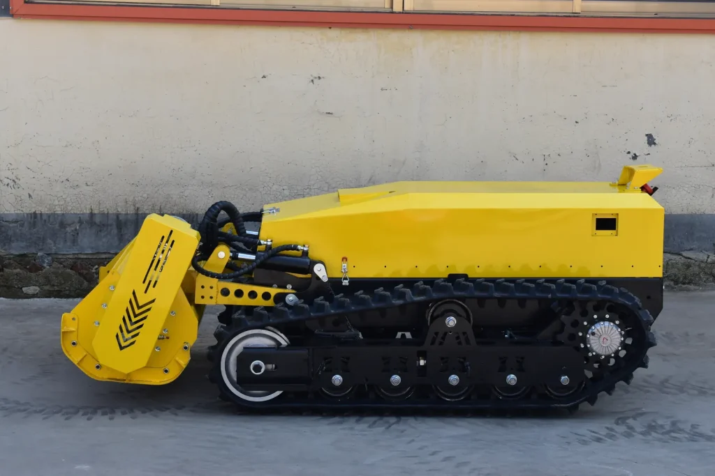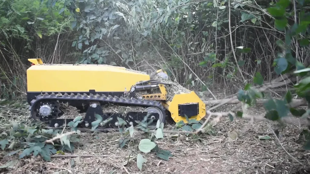

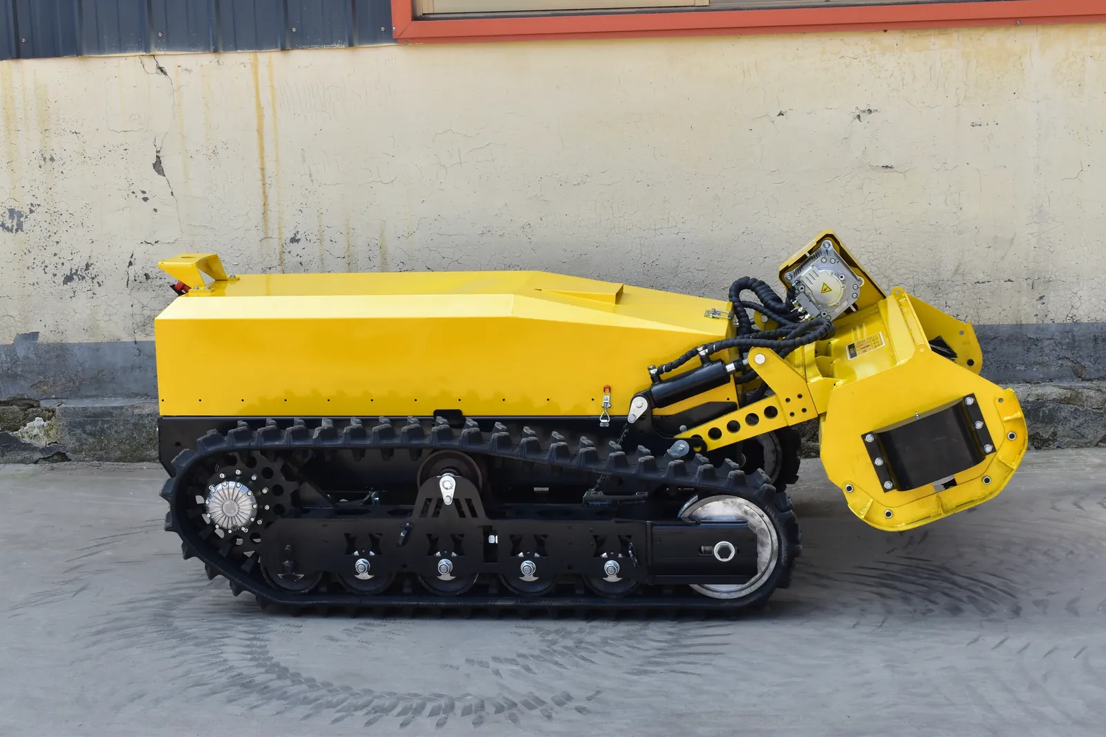
The cutting head is connected to the chassis through an arm and pivot arrangement. Hydraulic cylinders move that assembly between positions. Looking at the cylinder, arms and connection points together shows how the head is positioned.
This adjustment is part of matching the head to the work. The vegetation, ground and required finish all belong in the discussion, alongside the adjustment available on the machine.
Follow the connection from chassis to head
Start with a full side view. Find the arms between the chassis and the cutting head, then the pivot points at their connections. These joints allow the assembly to move as the hydraulic cylinders extend or retract.
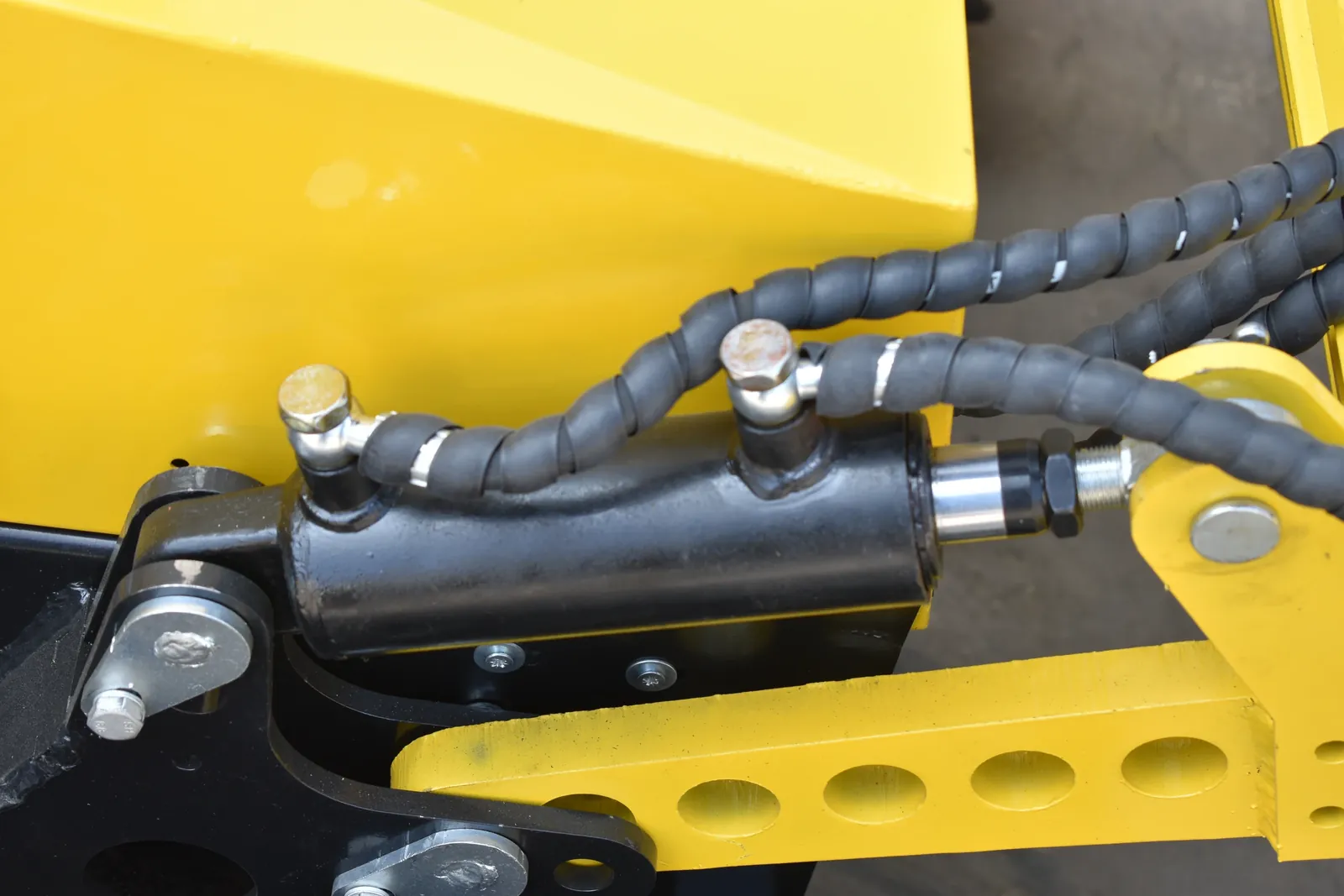
A close view adds the cylinder body, rod, mounting points and hoses. The cylinder supplies the movement; the connected arms and pivots define the path of the assembly. Keeping the complete layout in view makes those roles easier to understand.
Separate the three measurements
Several dimensions can appear in a lift specification. Each describes a different part of the arrangement:
- Cylinder stroke: the distance the cylinder rod moves.
- Head adjustment range: the movement of a specified point on the cutting-head assembly.
- Cutting height: the relationship between the cutting tools and the ground in the working position.
The linkage connects cylinder movement to head movement, so the measurement points matter. For a quotation or a comparison, ask where each dimension is taken. A photograph with the measurement points marked gives the number a clear meaning.
Connect head position with the cutting task
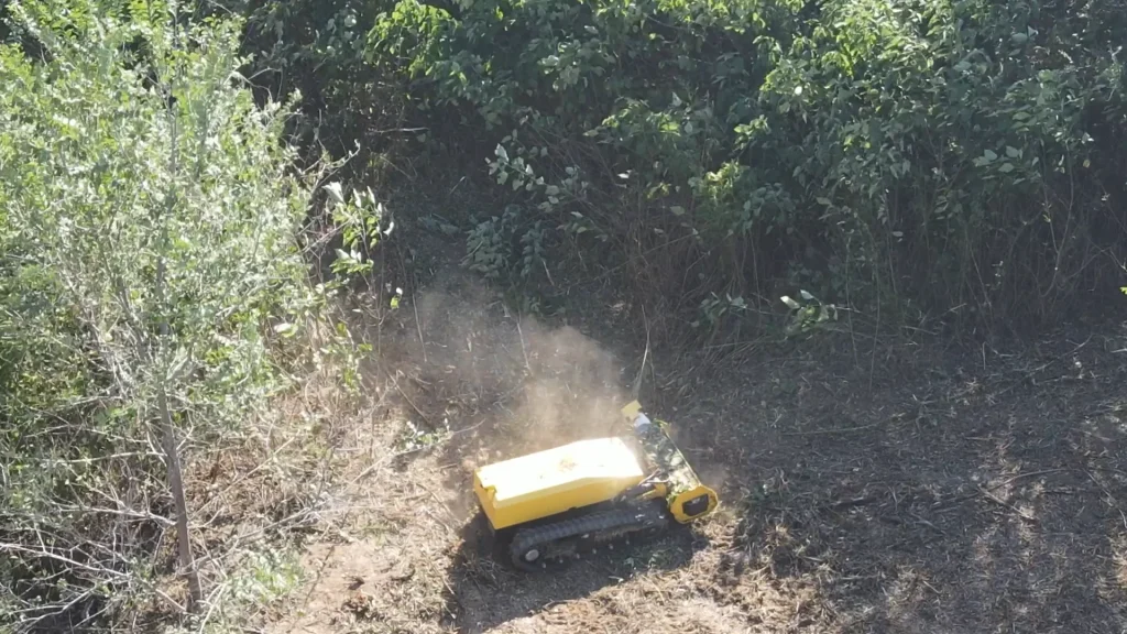
Describe the surface and the finish you need when discussing a lift arrangement. Show the growth and the ground beneath it, including the route the machine will follow. This helps us discuss the working position of the head alongside the cutting assembly.
Head position and forward feed are separate adjustments. In our guide to cutting-head feed, we explain how material entering the rotor changes the cutting load. The lift arrangement positions the assembly while the operator controls the advance into that material.
Keep the cutting tools out of the soil. Use the position and operating procedure specified for the supplied machine, with the required guards in place.
Look at the same machine through its movement
For a configuration discussion, ask for a full side view, a close view of the lift connections and a normal lift demonstration from one fixed camera position. Seeing the same machine in its lower and raised positions makes the available movement easier to follow.
Include the machine model and the working position you want to understand. We can then discuss the configuration, its adjustment range and the site requirements together.